
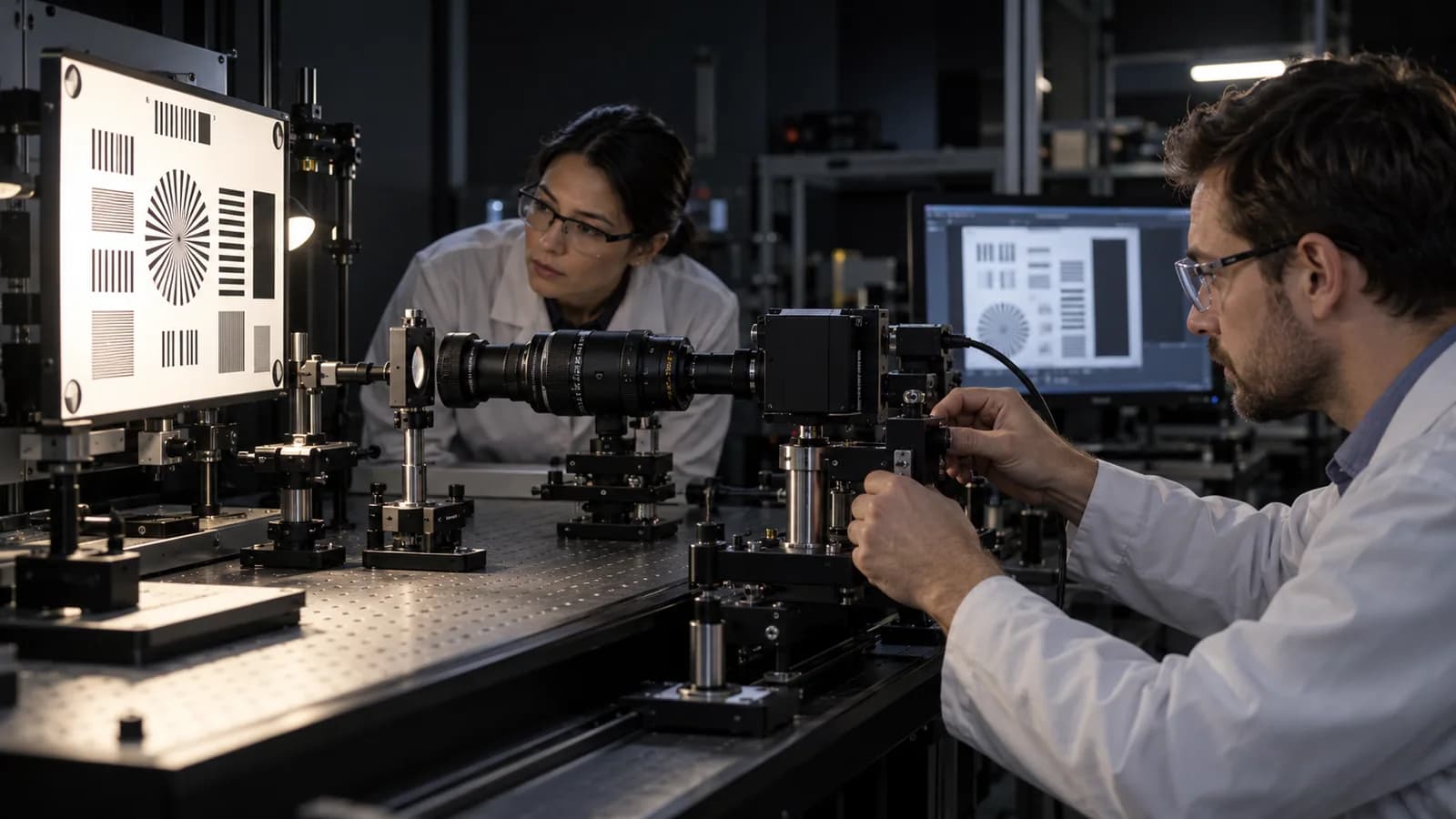
- RequirementConditions and acceptance criteria
- IntegrationOptics • mechanics • electronics
- EvidenceMeasurement and configuration
Make requirements measurable
“The image should be good enough” is not an acceptance criterion. Define viewing distance, observation conditions, alignment method, operating temperature and test setup to make the objective clear. The same image source can behave differently in different optical and mechanical assemblies.
In simulation and training hardware, distinguish the image presentation subsystem from scenario software. Developing display delivery and device interfaces does not imply that recognition, assessment or scenario models are included in the same delivery.
Interfaces change together
A mechanical position change can affect optical alignment; a power change can affect temperature and operating behavior. An interface document should therefore go beyond a pin list. Mounting references, cable routing, heat paths and service access belong to the same configuration.
An early prototype should measure the most uncertain interface. If alignment repeatability is under investigation, include removal and reinstallation in the test plan. Record the part revision and settings used to obtain each result.
Calibration and acceptance are different
Calibration establishes a relationship to a reference or supports adjustment; acceptance testing checks requirements under defined conditions. Completing an adjustment does not verify every operating condition. Acceptance evidence should identify the measurement setup, environment and uncertainties.
Gokbilge Tech’s optoelectronic and simulation hardware capabilities focus on this multidisciplinary integration space. This article is an engineering approach, not a product performance claim or a specific project architecture. Verification scope is defined with application requirements.
Want to apply this approach to your system?
Discuss your technical requirements →