
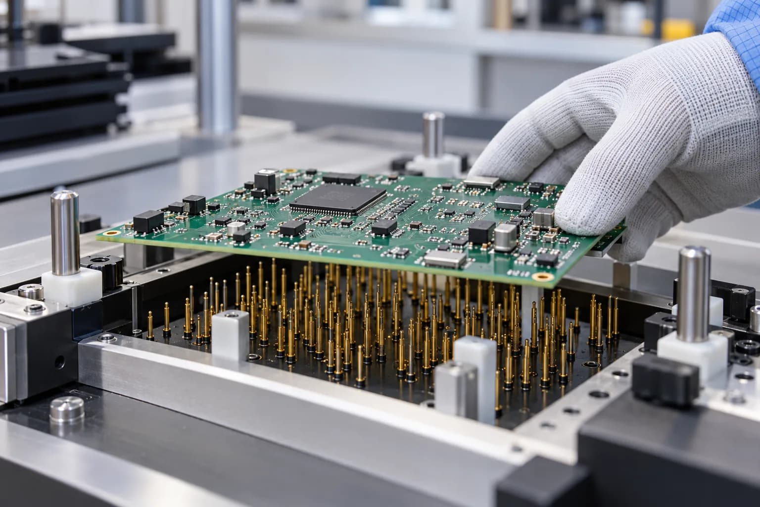
A working board does not validate a manufacturing process
A laboratory board may work with hand-reworked solder joints, selected components and an ideal supply. Production introduces assembly variation, component spread, programming steps and operator differences. Prototype success demonstrates feasibility under particular conditions, not that every manufactured unit will meet the same limits. Design verification and production screening consequently require different plans, evidence and acceptance decisions.
A useful manufacturing test goes beyond watching a device boot. It identifies which measurement detects each defect, which defects remain outside coverage and how a faulty fixture becomes visible. The aim is not necessarily to exercise every function for a long time, but to discriminate important manufacturing failures within a practical cycle-time and cost budget. The station itself is part of the measurement system and must be verified.
Derive coverage from a failure model
Start with defect classes: opens, shorts, reversed components, incorrect values, unprogrammed memory, broken communication paths and analog gain errors need different observations. An illuminated LED cannot validate every supply rail or sensor channel. Each requirement needs a stimulus, observation point, acceptance limit and prerequisite. This creates a coverage matrix tied to plausible failures rather than a checklist of functions that merely appeared to run.
Electrical checks, optical inspection and functional tests have different coverage. A supply may show the correct unloaded voltage but collapse under load; an internal loopback can pass despite a broken external connector. Stimulus and observation locations therefore matter. When a test uses internal points, the report must state which parts of the external path remain untested. Naming a step a functional test does not establish what it actually covers.
| Defect | Stimulus and observation | Coverage limit |
|---|---|---|
| Supply collapse | Voltage and current under defined load | Does not validate every temperature |
| Analog gain error | Multiple reference inputs | Reference and fixture uncertainty remain |
| Broken connector path | End-to-end test through the external interface | Does not establish mechanical lifetime |
Testability starts in PCB layout
Access to supplies, programming interfaces and critical signals is reserved during design. Probe spacing, support, contact force and board flex must be considered together. A test point can disturb a high-speed or sensitive analog path, so access is not independent of electrical behavior. Connector-based testing may be more appropriate than a probe fixture for some projects. Volume, coverage and cycle time determine the suitable approach.
Identity and programming paths also belong in the design. If a serial number exists only on a label, firmware or results may become associated with the wrong unit. The process defines when identity is read, who creates it and how it survives reprogramming. Mechanical and software controls prevent a fixture from accepting the wrong revision. Manufacturing data and test recipes remain versioned together rather than being maintained as unrelated documents.
Fixture faults can resemble product defects
Worn probes, contamination, loose cables and drifting references can reject good boards. An unintended connection between channels can also let a defective board pass. Station startup checks should not rely solely on a known-good unit. Known-defect cases or appropriate simulations verify that failures are still detected. The reference board itself requires controlled handling and periodic reassessment rather than being treated as permanently authoritative.
Retesting must not erase the initial result. First-pass, repeat and post-repair tests are distinct events. Intermittent contact problems cannot be investigated if only the final pass survives. Results retain station, fixture, instrument and software identities so clustering by shift or fixture can be reviewed. This traceability helps distinguish product defects from measurement problems before boards are unnecessarily dismantled or a design change is blamed.
Separate specification limits from measurement uncertainty
If the specification permits 3.20–3.40 V, the instrument and fixture uncertainty must inform the decision. Showing more decimal places cannot resolve a borderline result. Reference accuracy, cable drops, temperature and repeatability need examination. A guard band can reduce false acceptance while increasing rejection of conforming units. That tradeoff requires an explicit decision rule rather than an undocumented adjustment to make the production yield look better.
Product tolerance must not be replaced by the distribution observed at one station. Automatically widening limits to accommodate the first batch can normalize a defect. Specification, measurement method and manufacturing process are separate variables. Any limit change needs technical justification and revision control. Reporting uncertainty does not imply certification or accreditation; it makes the basis of the acceptance decision visible and exposes where additional measurement work is needed.
Section references: NIST · Measurement uncertainty ↗
Why a 96.3% pass rate is not a quality guarantee
Consider a wholly hypothetical batch of 1,000 boards with 30 defects. The screen detects 27 defects and incorrectly rejects 10 of the 970 conforming boards. It accepts 963 boards, including three defective units. First-pass yield is 96.3%, while the defect fraction among accepted units is approximately 0.312%. One quantity describes flow through the process; the other describes escapes. Neither can be substituted for the other.
In actual production, independent knowledge of every board's true condition is difficult to obtain. These illustrative numbers are therefore not measured performance. Fault-injection experiments can establish sensitivity to selected defect classes but cannot represent all unknown failures. Returned units and repair findings help extend coverage. A high yield alone cannot show what the screen misses; it can sometimes reflect inadequate testing rather than a healthy manufacturing process.
const assert = require('node:assert/strict');
// An illustrative accounting exercise, not a reliability estimator.
function screen(total, defective, detectedDefects, falseRejects) {
  for (const n of [total, defective, detectedDefects, falseRejects])
    assert(Number.isInteger(n) && n >= 0);
  assert(total > 0 && defective <= total);
  assert(detectedDefects <= defective);
  const good = total - defective;
  assert(falseRejects <= good);
  const escapes = defective - detectedDefects;
  const acceptedGood = good - falseRejects;
  const accepted = acceptedGood + escapes;
  return {
    accepted, escapes,
    firstPassYield: accepted / total,
    outgoingDefectFraction: accepted ? escapes / accepted : null,
    falseRejectFraction: good ? falseRejects / good : null,
  };
}
const result = screen(1000, 30, 27, 10);
assert.equal(result.accepted, 963);
assert.equal(result.escapes, 3);
assert.equal(result.firstPassYield, 0.963);
assert(Math.abs(result.outgoingDefectFraction - 3 / 963) < 1e-12);
assert.throws(() => screen(1000, 30, 31, 0));
assert.throws(() => screen(1000, 30, 27, 971));
console.log(result);
A production record needs more than pass or fail
A unit record includes identity, board revision, firmware digest, recipe, time, station and measured values. A failure code should point to a measurement and its expected limit, not only a test number. Later investigations need to identify which batch used which revision and programming image. Disconnected stations also require local persistence and reconciliation so missing evidence does not silently become an accepted production record.
Private design files, bills of materials and production details remain separate from public engineering content. Traceability does not require publishing every confidential artifact; it requires appropriate roles to access the correct evidence. Deliverable fields and retention are agreed early. Maintenance teams can then identify changes to a unit without exposing an organization's electronics design or sensitive manufacturing information outside the intended scope.
Evidence to request before production release
Review requirement-defect-test mappings, fixture checks and decision limits for the production candidate. Negative scenarios include programming failures, wrong revisions, duplicate identities and communication interruptions. Measure cycle time in the actual workflow, including loading and record validation. A fast measurement operation does not by itself establish a fast, reliable station when handling, recovery and evidence collection are included.
Acceptance covers more than yield: it identifies demonstrated detection, unresolved uncertainty and ownership of changes. An initial batch can validate a bounded process without becoming a lifetime or all-environment guarantee. The following checks help design and manufacturing teams agree on evidence. Numerical thresholds still depend on the actual product, risk, measurement method and intended production conditions.
- Does every critical defect have a stimulus, observation and coverage boundary?
- Were fixture-related false acceptance and false rejection investigated?
- Are initial, repeat and post-repair results retained separately?
- Are manufacturing data, firmware and recipe linked to the unit record?
Where Gokbilge Tech contributes
As an independent software and hardware house, Gokbilge Tech considers schematics, PCB design, manufacturing coordination, firmware, programming and test fixtures together. Local engineering contribution includes requirements, revisions, measurement and maintenance knowledge. Global components do not erase that contribution, but component origin and system-design responsibility must remain explicit. An engineering description is not a claim that every component was manufactured locally.
A discussion can begin with a sample board, intended use, existing failure records and a proposed production workflow. The scope of confidential material is agreed first. An initial assessment can identify missing test access, uncovered defect classes and an appropriate fixture approach. The worked example is not measured production performance of a Gokbilge product; it demonstrates how a concrete engineering scope can be defined.
Technical references
Want to apply this approach to your system?
Discuss your technical requirements →